INNOVATIONS THAT RESONATE

Coherent Electro-Optic Modulator
User Manual
Theory of Operation
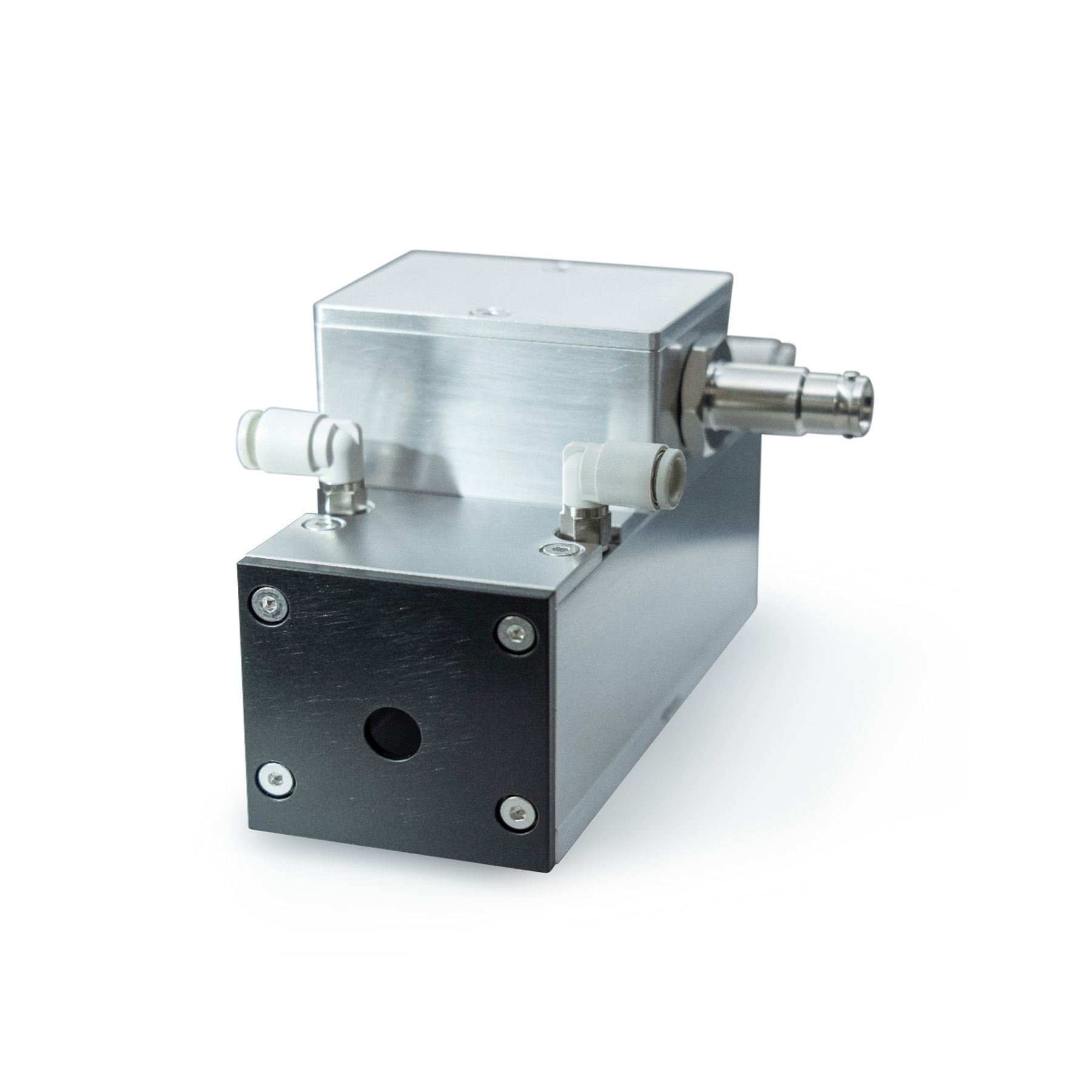
Coherent Electro-Optic Modulators act as voltage-controlled waveplates that can operate at nanosecond speeds. The crystal in an Electro-Optic Modulator becomes birefringent, or has refractive index which depends on incident light direction/polarization, when exposed to a large electric field. Electro-Optic Modulators become birefringent linearly proportional to the applied electric field, an effect known as the Pockels Effect or Linear Electro-Optic Effect. As such, Coherent Electro-Optic Modulators are commonly referred to as Pockels cells.
The voltage required to shift the phase of passing light by π, or half of a wave, is known as the Half-Wave Voltage (Vπ). In practice, this will rotate linearly polarized light polarization by 90 degrees. For the Electro-Optic Modulator, the Half-Wave Voltage is 9.5kV for 9.36μm incident light. The Half-Wave Voltage is directly proportional to the wavelength of incident light. Longer wavelengths require more voltage to reach Half-Wave modulation, while shorter wavelengths require less voltage.
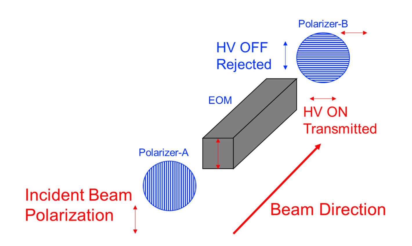
The ability to rotate linear polarization by 90 degrees in a matter of nanoseconds enables the device to be used as an ultra-fast optical shutter when placed between orthogonal polarizing filters. A diagram of the basic operation of an Electro-Optic Modulator may be found below:

Transmission of the Polarizer-EOS-Polarizer system is described by the following equation:

Where T is the percent transmission and Vπ is the half-wave voltage. This equation does not account for losses due to reflection, absorption, scatter, or diffraction.
Device Operation
Installation
- Use TFP-B to attenuate beam
- Optically align TFP-B
- Minimize transmitted laser power using TFP-B, lock rotation
- Set TFP-A approximately orthogonal to TFP-B
- Rotate TFP-A until enough light passes to optically align
- Optically align TFP-A
- Install and optically align EOS
- Remove EOS
- Minimize transmitted laser power using TFP-A(orthogonal to TFP-B), lock rotation
- Replace EOS
- Connect cooling to EOS and HV driver
- Verify HV power supply and HV driver are grounded to same grounding plane
- Connect HV supply to HV driver
- Connect HV driver to EOS
- Connect TTL/control signal to HV driver
- Connect AC to HV driver
- System is set up
Verification
With HV OFF, EOS disconnected, driver ON, control signal ON and connected:
- Place oscilloscope probe near output of driver, the oscilloscope probe should pick up some EMI/noise at the rise and fall of the TTL (set scope to lowest voltage reading and highest sample rate). It may be useful to connect a second output from TTL generator to oscilloscope to assist in located rise and fall locations.
- If no EMI/noise signal is observed, verify connections, power, and grounding. If issue persists, contact Coherent Corp.
Synchronization
Once aligned and verified, the electrical pulse must be synchronized with laser pulse.
With HV OFF, EOS out of beam path and disconnected, driver ON, control signal on and connected:
- Connect a fast optical detector to an oscilloscope on one channel (with proper attenuation) and a probe near the output of the driver.
- Adjust delay of control signal going to driver until EMI/noise caused by HV driver rise/fall time aligns with desired output optical detector. This should make it much easier to find and tune the HV pulse to the optical pulse.
With EOS aligned and connected, driver ON, control signal on and connected:
- Turn voltage set point potentiometer to lowest value before turning on HV
- Connect a fast optical detector to an oscilloscope on one channel (with proper optical attenuation)
- Turn up voltage setpoint to about ¼ full scale. Some optical signal should be visible. If so, fine tune the electrical pulse width and delay to match desired output. If no optical signal is detected, slowly adjust the delay of the EOS until the laser pulse is found.
Operation
Once the electrical pulse is synchronized with the laser pulse, then the system is ready for use.
EOS system will transmit when control input is triggered with a 5V signal. Pulse width and frequency may be adjusted as desired within the specified safe operating range. EOS performance has slight dependence on pulse width and frequency. Please contact Coherent representative with questions about pulse width and frequency dependence of operation.
Troubleshooting
Problem |
Potential Root Cause(s) |
Potential Solution(s) |
Does not transmit laser pulse when triggered |
HV supply is OFF or disconnected, HV driver is OFF or disconnected |
Verify all connections and power according to installation instructions |
HV driver is not synchronized to laser pulse |
Resynchronize HV driver and laser pulse according to synchronization instructions |
|
HV driver and supply are not grounded properly |
Verify HV supply and HV driver are connected to the same low-impedance grounding plane with as little physical separation as possible |
|
Transmitted beam power or location is unstable |
Back reflections off EOS optical surface causing instability in laser |
Tip/tilt EOS to prevent back reflection |
Pointing shift exceeds specification |
Insufficient water cooling |
Verify water cooling loop is running within the specified ranges for flow and pressure |
HV power supply showing fault status |
Electrical short circuit |
Immediately turn off HV. Wait 5 minutes for residual charge to dissipate. Disconnect EOS. Inspect EOS for leaks or signs of electrical damage on optical surfaces. Contact Coherent Corp. if signs of leaks or electrical damage is present. |
Low transmission |
Improper TFP orientation |
Refer to installation instructions. TFP-A should transmit the incident beam polarization and TFP-B should reject the incident beam polarization |
Improper system alignment |
Verify proper alignment according to installation instructions |
|
Crystal damaged |
Inspect EOS for signs of physical damage i.e. being dropped or impacted. If EOS crystal is broken, it will need to be returned to Coherent Corp. for repair evaluation. |
Additional Information
HV Power Supply Interface
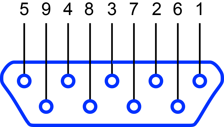
Remote control of HV power supply uses D-sub 9 pin connector type. Pin out diagram below:

1 |
DGND |
Digital ground |
2 |
FAULTY/FUNCTIONAL |
OC output; OPEN=SPARK or FAULTY or STOP WORKING, CLOSE=FUNCTIONAL |
3 |
VDEM |
To be defined |
4 |
GND |
Analog ground |
5 |
VFBK |
Voltage feedback 0 to 5V=0 to 10kV |
6 |
L/R MODE |
To be defined |
7 |
HV INHIBIT |
0V or FLOATING=ON, 12V=OFF |
8 |
IDEM |
To be defined |
9 |
IFBK |
Current feedback 0 to 5V=0 to 30mA |
Revision C. November 30, 2023