Laser Optics
What are Laser Optics?
Laser optics are components specifically intended for manipulating laser light, which is typically coherent and monochromatic, frequently polarized, and sometimes of high intensity. The form and applications of laser optics are so diverse that it is difficult to generalize about them, but they must nearly always be fabricated to high precision to operate successfully.

Laser optics are as varied as the applications they service, ranging from fiber communications micro-optics through meter-class telescope mirrors. They manipulate laser beams through virtually every type of light/matter interaction, including refraction, reflection, diffraction, polarization, and spectrally selective processes, non-linear effects, and even scattering.
The fabrication of laser optics employs a similarly diverse toolbox. This ranges from traditional grinding and polishing (with their automated and computer-controlled variations) to single-point diamond turning, lithography, an array of molding and replication methods, holographic techniques, and a spectrum of thin-film coating processes.
However, there are a few unifying factors amongst laser optics. First, they almost invariably need to maintain the original wavefront quality of the laser beam. This is essential to preserving the very qualities that make laser light unique, like spatial brightness and coherence. Wavefront distortion introduced by the optics limits system efficiency and the ability to focus the laser and maintain its beam profile. This applies to most applications, whether it’s materials processing, surgery, microscopy, flow cytometry, or telecommunications. In terms of fabrication, minimizing wavefront distortion usually requires making optics with highly accurate surface shapes and using very homogenous materials.
Laser optics must also typically produce minimal scatter because this can reduce laser system efficiency and introduce noise. This reduces performance in everything from imaging through materials processing. Minimizing scatter is also a key factor in avoiding laser-induced damage for high-power laser optics. The first step in fabricating low scatter optics is usually producing component surfaces with low surface roughness.
Laser optics are virtually always thin film coated, with the prominent exception of Brewster windows. Again, this is typically done to enhance performance. For example, most transmissive laser optics use antireflection coatings to maximize throughput and minimize spurious (ghost) reflections. Thin film coatings are often more durable than the optic’s substrate material, so coatings can also be used to protect the optical surface and extend component lifetime. The Coherent diamond over-coat (DOC) is a standout example of this.
Given the truly vast scope of this topic, this article will just provide an overview of some of the most significant, broad classes of laser optics. These are described in the following, and this list is by no means comprehensive.

Lenses
Lenses are refractive transmissive optics that either concentrate or spread laser light in one or two dimensions. Since they are predominately used with monochromatic light, chromatic aberration (the change in lens focal length with wavelength) is rarely a concern for laser lenses. For this reason, single-element lenses (that have no color correction) are adequate for many simple tasks in which the optics operate totally on-axis. Examples are beam-expanding telescopes and focusing and collimating lenses. In fact, a single-element focusing lens with an aspheric surface shape can deliver on-axis performance at essentially the diffraction limit (best performance theoretically possible).
However, more complex, multi-element lens systems are invariably required in at least two other instances. The first is low f-number systems (f-number = lens system focal length/aperture). Especially below f/3, the performance of most single-element spherical lenses departs substantially from the diffraction limit. Multi-element spherical surface focusing lenses, as well as aspheric surfaces, are used to address this.
The second application for multi-element systems are those that don’t operate purely on-axis but must cover a specific field of view. F-theta scan lenses are an example of this. Multiple elements are required to create an optic that focuses on a plane (rather than a curved surface) over a range of angles, and which also achieves good focused spot size at the edges of the field.

Mirrors
Metal-coated mirrors, particularly with silicon, copper, aluminum, and gold, are frequently used for reflecting visible and infrared laser beams. For CO₂ lasers which output around 10 µm, it’s not uncommon to make mirrors from metal substrates, and simply use the bare polished metal surface as the mirror. The advantage of metal and metal-coated mirrors is typically lower cost.
Thin film coatings are employed when higher levels of reflectivity are required, to achieve higher laser damage threshold levels, or when precise polarization control is necessary. The simplest laser line thin film reflector is typically a stack of alternating high and low refractive index materials, each of which is one quarter-wave thick at the laser wavelength. By building up many layers of this type, reflectance values of over 99.9% are routinely achieved.
However, a mirror with a coating of this type is relatively narrowband. That means it can’t be used at wavelengths other than the exact laser wavelength it was designed for. Also, the peak reflectance of all thin film mirror coatings shifts with angle. So, a laser line mirror designed for use at 0° angle of incidence can’t be used at 45°, and vice-versa. Broadband all-dielectric (thin film) mirrors can be designed which are usable over a wider range of wavelengths and angles of incidence. But there is a small sacrifice in the value of peak reflectance with these.
Beamsplitters
Beamsplitters are optics which reflect some of the incident laser energy and transmit the rest. This effect may be highly polarization-dependent. Sometimes this is a drawback, but in other cases it is specifically exploited to either separate or combine orthogonal polarizations.
A beamsplitter can also be wavelength dependent. In this case, it might be used to separate two co-axial laser beams having different wavelengths. An example of this is a dichroic beamsplitter that reflects the fundamental wavelength (1064 nm) of a Nd:YAG laser and transmits its second harmonic (532 nm).
The most common formats for beamsplitters are the cube type and plate type. A cube type beamsplitter is comprised of two right angle prisms joined together at their hypotenuses to form a cube. The beamsplitter coating goes on the hypotenuse of one of the prisms. The other four faces are typically antireflection coated.

Cube and plate-type beamsplitters perform the same function but are constructed very differently. This gives them different characteristics, resulting in advantages and disadvantages in various applications.
A plate-type beamsplitter is a plane parallel (or often slightly wedged) plate. The beamsplitter coating is typically encountered on the first surface, and the second surface has an anti-reflection coating.
Both cube and plate-type beamsplitters have their unique characteristics, leading to advantages and disadvantages in various applications. For example, plate-type beamsplitters are typically more compact and lighter, and also less costly to produce. But, when used at anything other than 0° angle of incidence, they produce an unwanted secondary reflection that is offset from the main reflected beam. They also offset the transmitted beam, which can make system design more complex and alignment more difficult.
Cube beamsplitters eliminate the problem of an unwanted secondary reflection, and any offset in the transmitted beam. They also typically work better over a wider range of incidence angles. It’s also easier to produce cube beamsplitters with coatings that are less sensitive to polarization and which function over a broader range of wavelengths. But cube beamsplitters can be less durable and more sensitive to temperature changes.
Polarization Components
Most lasers emit polarized light, and there are numerous different optics and devices designed to manipulate, analyze, or exploit this polarization. The conceptually simplest optic is the linear polarizer. It just passes light with a polarization oriented in a specific direction and blocks light polarized in any other orientation. A linear polarizer can be used to perform many functions. If it is rotated in a polarized laser beam it acts as a variable attenuator – a dimmer switch for a laser!
One of the most basic optics that alters the polarization state of a laser beam is the quarter-wave plate. These convert linearly polarized light into circularly polarized light, or the reverse. Half-wave plates rotate the polarization direction of input linearly polarized light. This rotation can be smoothly varied from 0° to 90° as the half-wave plate itself is physically rotated.
Polarization rotators and linear polarizers (or polarizing beamsplitters) can be combined to make Faraday isolators. These are “one-way valves” for light. These are particularly useful devices for preventing reflected light from re-entering a laser, which could cause damage or induce operating instability. Faraday isolators quite commonly perform this function in high-power industrial laser systems.
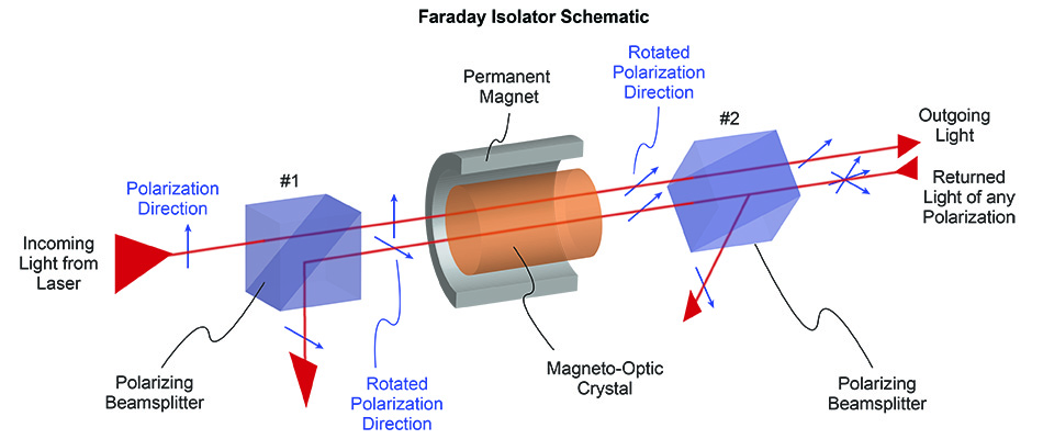
Faraday isolators use a combination of polarizing beamsplitters and a magneto-active crystal (which rotates the polarization plane of light by 45°) to yield a device which passes a laser beam in only one direction.
A more sophisticated polarization-based laser optic is the electro-optic modulator (EOM). Like the Faraday isolator, it employs a crystal that rotates the polarization plane of transmitted light. But, in this case, the effect is controlled by an applied electric field rather than a magnetic field. This is called the Pockels Effect.
To make an intensity modulator, the electro-optic crystal is paired with a linear polarizer. When the polarization plane of the input laser beam aligns with the linear polarizer, the beam is transmitted. When the applied voltage is adjusted so that the crystal rotates the beam polarization by 90° relative to the linear polarizer, then the beam is blocked. By varying the voltage, the transmitted laser beam intensity can be modulated, typically at speeds of up to several MHz.
High Energy Laser (HEL) Optics
There is no specific definition for exactly what constitutes high-energy laser optics, but essentially these are components that are used with lasers having high peak energy or fluence values. Specifically, this means power levels that would damage most optics produced using traditional means, or at least significantly reduce their useful lifetimes.
There are many mechanisms of laser-induced damage and they depend upon several factors, including the laser wavelength, pulse energy, peak power, pulse shape, and more. But most damage tends to occur through either heating caused by bulk absorption, dielectric breakdown induced by the high electric field of the laser pulse, or avalanche breakdown caused by multiphoton absorption.
The functionality of high-energy laser optics is the same as has already been described (lenses, mirrors, polarizers, etc.). But, the materials, polishing, and coating of these components must be controlled extremely carefully in order to minimize the various damage mechanisms when in operation.
This often starts with material selection. Namely choosing substrate materials that inherently demonstrate high laser-induced damage threshold (LIDT) and low absorption at the operational wavelength. Of course, the actual materials themselves must be of high purity and quality. Then, every step of subsequent processing (shaping, coating, and even packaging) must be carefully monitored and controlled to minimize contamination. HEL optics are usually made in clean room environments.
Surface roughness often plays a part in LIDT, so specialized polishing techniques are frequently used in HEL fabrication. The polishing abrasives used may even be specifically selected to minimize contamination and subsequent damage.
Producing thin film coatings for HEL optics is an entire discipline in its own right. Again, the materials used, and their purity, is fundamental. In addition, the coating design may be specifically optimized to enhance thermal conductivity and heat dissipation. Also, the coatings might be designed to suppress nonlinear optical effects, such as harmonic generation or self-focusing, which are more pronounced at high energy levels.
Ultrafast Optics
Optics and coatings for ultrafast lasers (pulse durations in the femtosecond or picosecond range) are another distinct class of components. There are two primary reasons for this.
First, ultrafast lasers are not as monochromatic as most other lasers. This is because the fundamental physics of ultrafast lasers dictates that as the pulsewidth gets shorter, the spectral bandwidth (range of wavelengths) of the output increases. For example, the 12 fs pulses produced by the Coherent Vitara laser are centered at 800 nm, but have a bandwidth of about 100 nm.
The second differentiator for ultrafast optics is that they often have very high peak powers. These power levels can cause the issues with laser-induced damage mentioned previously.
The key problem caused by the larger bandwidth of ultrafast pulses isn’t chromatic aberration as it might be for imaging optics used with visible light. Instead, the issue is group velocity dispersion (GVD).
GVD occurs because the different wavelength components of an ultrafast pulse travel at slightly different velocities through a material. So, when an ultrafast pulse goes through an optic or coating, the shorter wavelengths emerge a bit later than the longer wavelengths. This increases the pulse length.
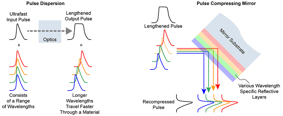
Ultrafast pulses are not monochromatic but consist of a range of wavelengths. The shorter the pulse, the broader this spectral spread. When an ultrafast pulse passes through a material, dispersion causes the shorter wavelengths to move slower than the longer wavelengths. This spreads the pulse out in time – the pulsewidth increases. A pulse-compressing mirror makes the faster wavelengths travel farther into the coating to reverse this effect.
An increase in pulse length creates several problems, depending upon the use. For one, it lowers the temporal resolution in applications like time-resolved spectroscopy. It also reduces the pulse peak power which affects any application that depends on nonlinear phenomena, such as multiphoton imaging or CARS spectroscopy.
One important class of ultrafast optics are ‘dispersive mirrors.’ These are thin film-coated high reflectors specifically designed to manage dispersive effects in ultrafast laser pulses.
These optics work on a conceptually simple principle. They essentially consist of a stack of multiple high reflector coatings, each tuned to a slightly different wavelength.
Now consider a design where the shorter wavelength reflectors are at the top of the coating and the longer wavelength reflectors are placed deeper in the stack. The longer wavelengths must travel farther through the coating before being reflected, which takes more time and allows the ‘slower’ components of the pulse to catch up with them. This has the effect of recompressing a pulse which has been spread because it previously went through another dispersive component.
Dispersive mirrors are often used to purposefully lengthen a pulse. For example, a pulse might be lengthened with a dispersive mirror before entering an amplifier. This lowers its peak power and reduces the potential for damaging the amplifier optics due to very high laser fluence. After the pulse is amplified, it is recompressed back to its original shorter pulsewidth with another dispersive mirror having the opposite effect to the first one. This is called chirped pulse amplification (CPA).
This overview has only touched upon a few types of laser optics, and provided simplified explanations for how they work and why they are used. Learn more by exploring the extensive range of Coherent laser optics.